Distributed acoustic localization
Microphone self-calibration and drone tracking
I’m developing a self-calibrating microphone array to localize a drone that I built. The work spans acoustic inference, simulation, and embedded hardware.
1. Array self-calibration
Let mi ∈ ℝ³ be the position of microphone node i, and c the assumed uniform speed of sound. Each node has a speaker for two-way ranging. Node i measures round-trip interval Δi; node j measures its receive-to-reply interval Δj. Treating each node’s speaker and microphone as co-located, assume stationary nodes, reciprocal propagation, and calibrated emission/reception latency. With clock rates expressed in common seconds, the distance estimate is
For affine clocks τi(t) = ait + bi, local time differences eliminate the offsets bi. Unequal rates ai still require correction; the current ranging primitive assumes negligible rate mismatch over an exchange.
Given measured pairs E and nonnegative weights wij, the geometry-recovery target is
Here N is the node count and ‖·‖ is the Euclidean norm. Distances do not fix translation, rotation, or reflection; a coordinate convention or external anchors must remove those ambiguities. An insufficiently constrained measurement graph can admit further solutions. This geometry solver is planned.
2. Source localization
After clock correction, let δ̃ij be the measured arrival time at i minus that at j for the same emission. For a source position x ∈ ℝ³, neglecting motion during the measurement, the range-difference residual is
The planned position estimate minimizes the weighted sum of squared residuals over detected pairs. Residual clock offsets add a bias to δ̃ij; poor array geometry and sources far beyond the array aperture weaken range observability. Timing calibration and array calibration therefore belong to the same estimation problem.
3. Simulation and hardware
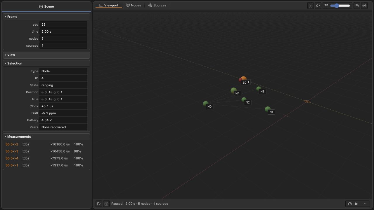
The simulator propagates modulated acoustic packets and known source chirps into microphone audio frames. The working core performs peer discovery, two-way ranging, and matched-filter chirp detection. Arrival-time differences are computed from detector timestamps; missed detections produce missing measurements.
Geometry recovery, clock synchronization, general-sound delay estimation with GCC-PHAT, and the source-position solver remain under development. The simulator and 3D viewer provide reproducible scenarios for developing these estimators.
The hardware design uses ESP32-S3 nodes, ICS-43434 I2S microphones, and MAX98357A amplifiers with speakers. Firmware integration and physical measurements of ranging error, clock drift, and acoustic noise are ongoing work toward tracking my self-built drone.