VoxelKernel
Constraint-driven geometry and computational engineering
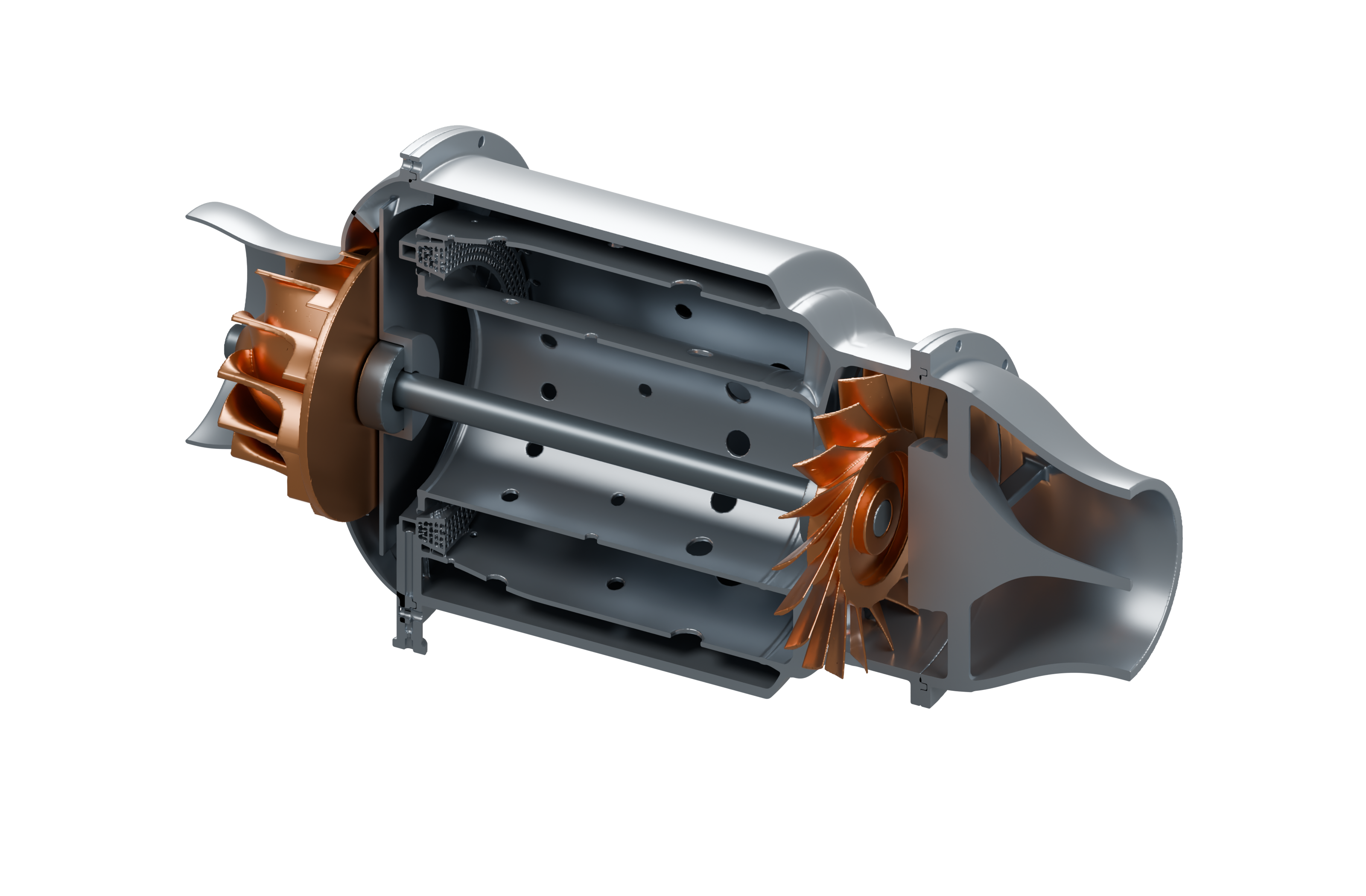
I develop VoxelKernel to generate geometry from physical requirements. It couples physical models, constrained design search, and implicit solid geometry. Applications include a microturbojet under active development and a rocket engine verified against the implemented geometry and reduced-order engineering checks, with physical testing planned.
1. Implicit solids
For design parameters x, a scalar field φ defines a solid Ω by its nonpositive region. Negative values denote interior points. Union and cutting fields are constructed pointwise by:
For signed-distance inputs, their nonpositive regions are A ∪ B and A ∖ int(B): the cutting boundary is retained. The resulting fields need not remain exact signed distances. Distance-dependent offsets therefore require an appropriate distance representation. Sparse sampled fields support swept passages, walls, and bounded junction blends. Grid spacing limits representable thickness and clearance; successful meshing alone cannot establish that a thin feature survived discretization.
2. Finite constrained design search
Let Xr be the finite Cartesian set of candidates in search round r, and u(x) the computed physical state. Scalar requirements gi and Boolean predicates bj define feasibility. If at least one search round contains a feasible candidate, the discrete selection target is:
Physical states must converge within specified residual tolerances and remain inside model validity domains. Constraints include temperatures, pressure budgets, material strength, and topology. The objective J is application-specific: chamber-shell volume for the rocket, envelope volume for the microturbojet.
The implementation enumerates candidates deterministically and stops after the first feasible round, or reports that no feasible sampled candidate was found. Numerically tied objectives use the worst normalized constraint margin, then enumeration order. Selection is limited to that round’s sampled set and objective-comparison tolerance; it does not establish a continuous or globally optimal design. Rejected candidates, numerical failures, and constraint margins remain in the audit record; final geometry receives separate checks.
3. Microturbojet: coupled operating point
The microturbojet couples compressor, combustor, turbine, and nozzle models through mass flow, pressure, temperature, and shaft power. With mechanical efficiency ηm, turbine power Pt, and compressor demand Pc, the shaft closure is:
Geometry-derived passage areas and combustor pressure loss feed back into the operating point. Compressor mean-line losses draw on Galvas [1]; turbine off-design and clearance models draw on AXOD [2] and NASA experiments [3]. Liner orifice balances use combustor [4] and discharge-coefficient research [5]. The combustor loss estimate remains a lower bound, omitting expansion, friction, heat-addition, and mixing losses.
The microturbojet remains under active development.
4. Rocket engine: coupled cooling and structure
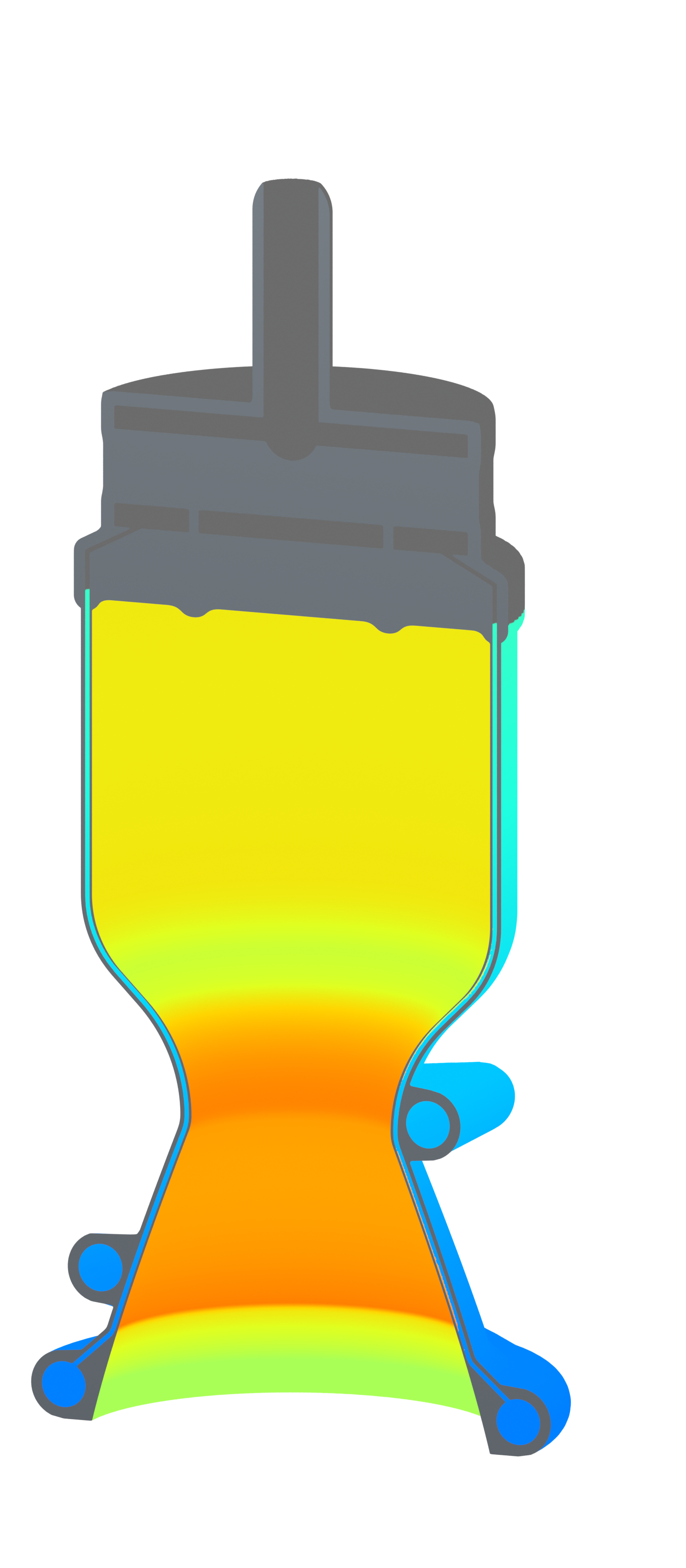
The pressure-fed rocket combines isolated fuel/oxidizer plenums, a nozzle, and regenerative cooling. Classical chamber and nozzle relations follow NASA references [6] and [7]; optional CEA thermochemistry [8] supplies equilibrium properties. Cooling paths also define the pressure-wall envelope, coupling thermal analysis to generated dimensions.
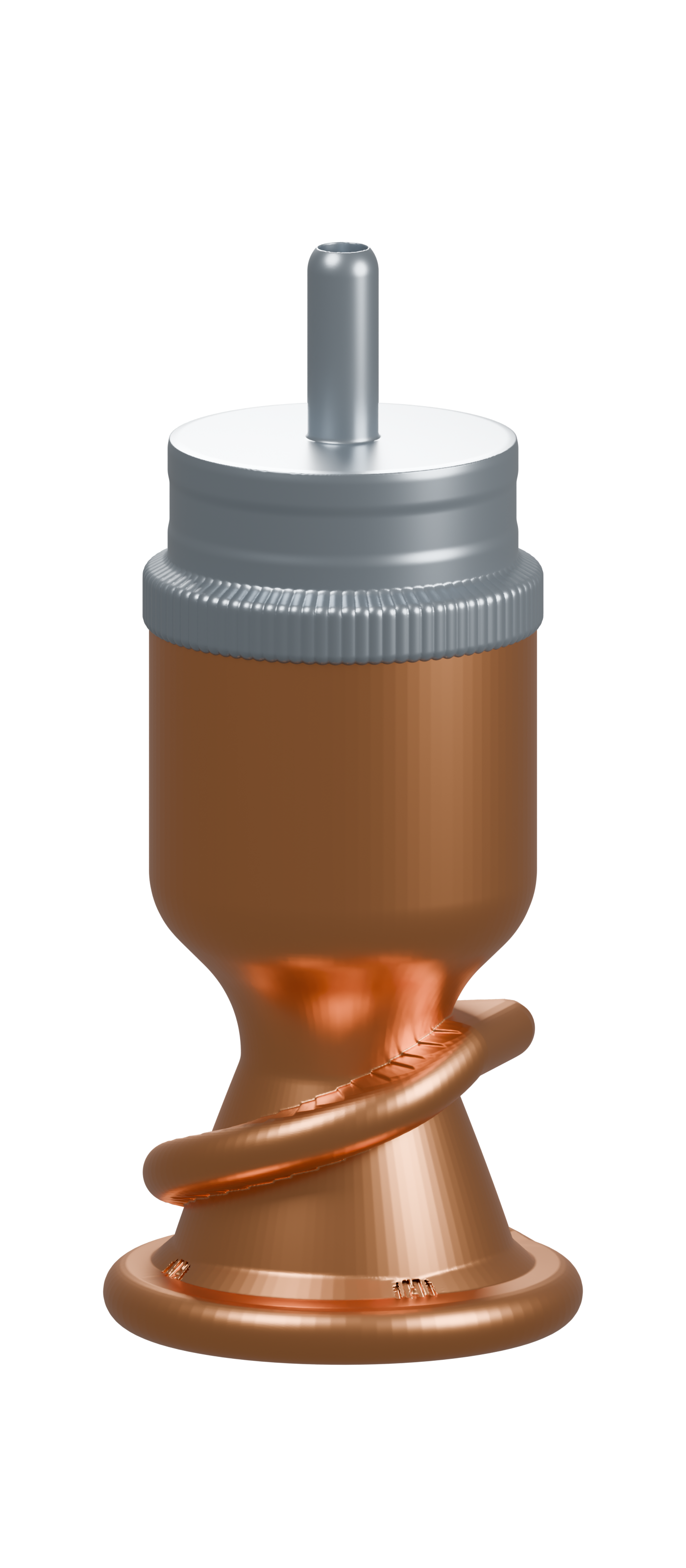
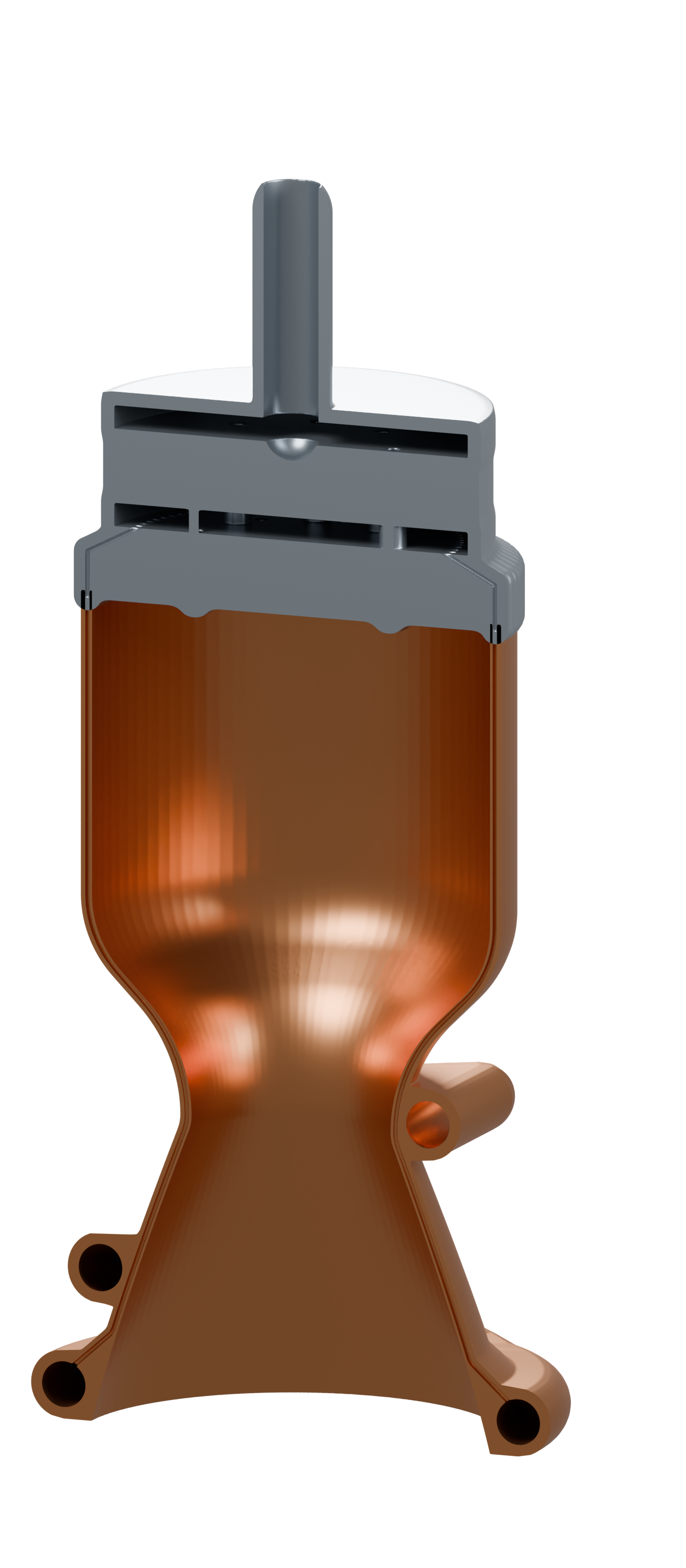

The cooling circuit satisfies nodal mass conservation and branch pressure-loss laws:
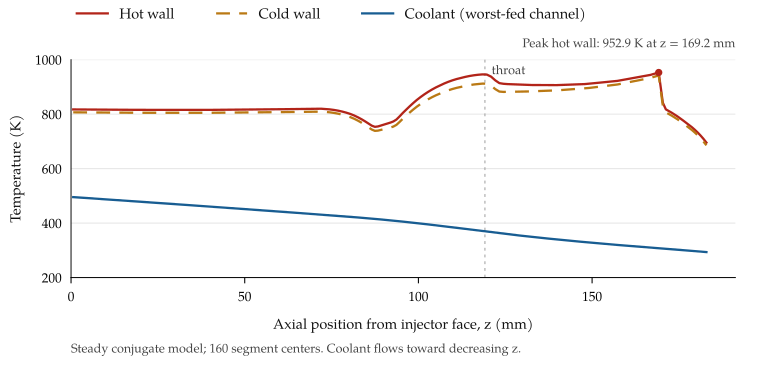
Here A is the node–branch incidence matrix, positive at each branch’s origin; ṁ contains signed mass flows, s external supply, P piezometric pressures, T the coolant temperature state, and ℓ branch pressure losses. Prescribed boundary pressures close the system. A global-gradient solve and outer thermal iteration resolve unequal channel flows; the worst-fed channel is checked at its solved condition.
Bartz gas-side heat transfer, one-dimensional wall conduction, and a coolant energy march determine temperatures. Temperature-dependent conductivity and strength enter a Lamé thick-cylinder yield screen. Feasibility requires adequate cooling pressure, vapor-pressure margin, ligament thickness, energy closure, and yield safety factor. These are reduced-order models, excluding combustion transients, radiation, and full thermo-mechanical finite-element analysis.
5. Helical heat exchanger
My implementation of LEAP71’s HelixHeatX reproduces its geometry in VoxelKernel. The original design is LEAP71’s, released under Apache 2.0. Two disjoint fluid domains wind through 10.5 turns, with separating walls, internal fins, and external ribs.
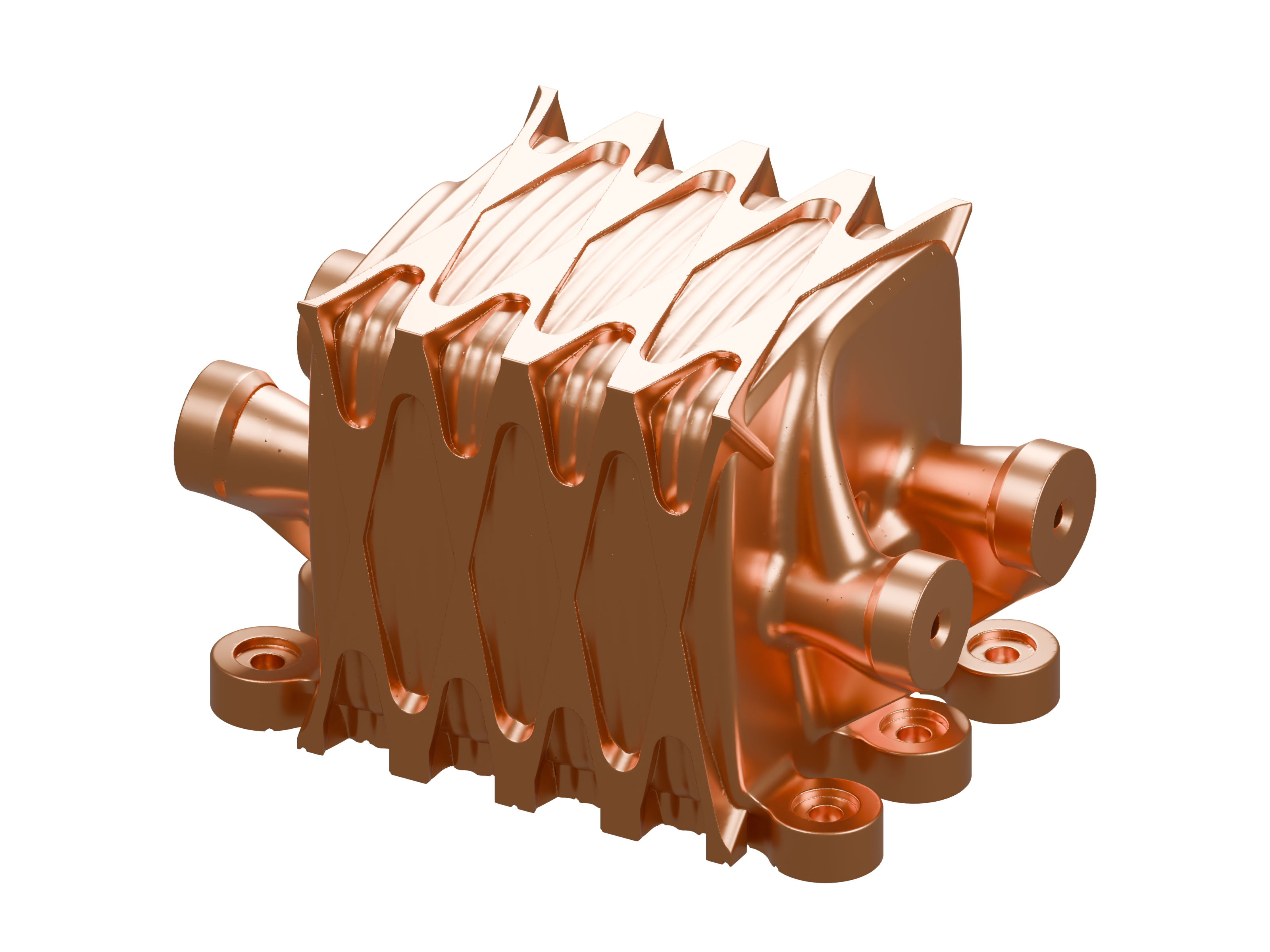
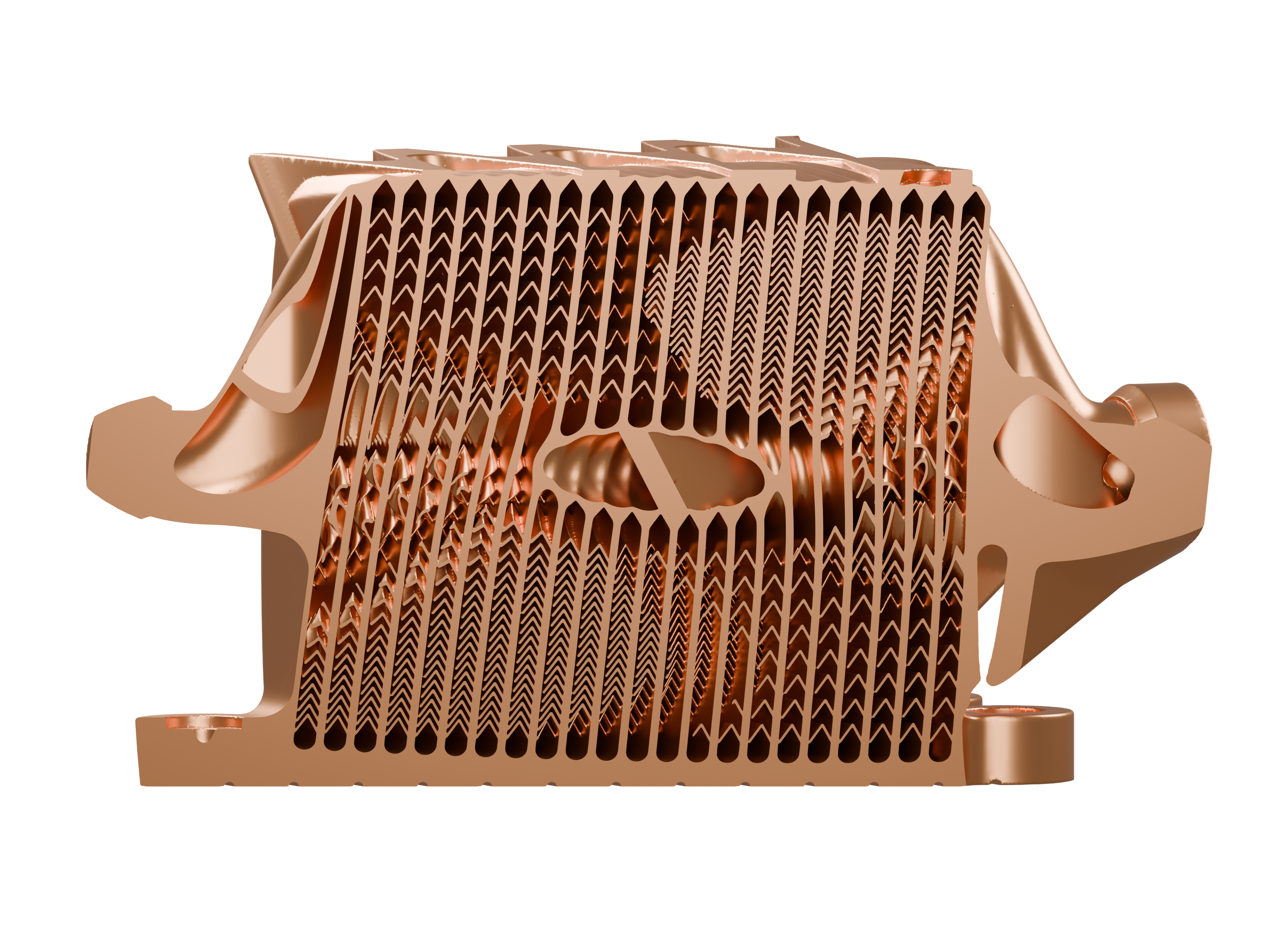
The geometric requirements are connected hot and cold domains, no fluid overlap, and sufficient material separation.
6. Geometric verification
Geometric verification evaluates connected solid and fluid domains, enclosed voids, clearances, and manufacturing dimensions. Surface topology and passage connectivity are checked separately from the thermal and fluid models.
Engineering references
- M. R. Galvas. FORTRAN Program for Predicting Off-Design Performance of Centrifugal Compressors. NASA TN D-7487, 1973.
- A. J. Glassman. Modeling Improvements and Users Manual for Axial-flow Turbine Off-design Computer Code AXOD. NASA CR-195370, 1994.
- S. M. Futral Jr. and D. E. Holeski. Effect of Rotor Tip Clearance on the Performance of a 5-Inch Single-Stage Axial-Flow Turbine. NASA TM X-1757, 1969.
- R. R. Tacina and J. Grobman. Analysis of Total-Pressure Loss and Airflow Distribution for Annular Gas Turbine Combustors. NASA TN D-5385, 1969.
- R. T. Dittrich and C. C. Graves. Discharge Coefficients for Combustor-liner Air-entry Holes. NACA TN 3663, 1956.
- D. K. Huzel and D. H. Huang. Design of Liquid Propellant Rocket Engines. NASA SP-125, second edition, 1971.
- Liquid Rocket Engine Nozzles. NASA SP-8120, 1976.
- NASA Chemical Equilibrium with Applications (CEA). Thermochemical equilibrium and transport-property calculations.